

Last year I thought the BITX40 was “done”. It successfully worked on 80, 40, 30, and 20m. It was truly multi-band! The trick to doing that was to make the Band Pass and Low Pass filters pluggable using QRP Labs filters. One only needed to open the radio, change the filters, and retune the VFO. It worked well, with one exception: The circuit layout required the use of the RD15HVF1 PA amp rather than the IRF510. One can never leave well enough alone however, and that’s when things started going downhill.
First, I got a new case, printed by Wolfland Computers (Link on right —> ), and you can even go buy one. Second: I LOVE this case. That is because I designed the basic concept! Wolfland turned it into what it is though, and it took a few iterations to get it right. 3D printing stuff is hard! So in Feb 2018 I had this case and a perfectly working radio, and I wanted to marry the two. The issue was that the case doesn’t lend itself to being opened all the time for filter changes. What to do? The decision was made to turn it into a dual band radio and use automatic switching based on VFO frequency.
Arduino, here we come!
To make this happen I had to graduate from the QRP Labs VFO and roll my own. What I decided to do was use the QRP Labs Arduino Shield which integrates with their Si5351A Synthesizer Module kit, which I already have. I already had an Arduino Uno clone so I ordered up a 16×2 LCD with i2c control and started work.
First I had to find a sketch to hack on, and in the end I decided to use the stock uBITX sketch. It has rotary encoder tuning built in, LSB/USB switching, and can control relays based on the tuned frequency. These were all my desired features! This also meant modifying the BITX40 board to use the Si5351A output for the BFO and the VFO, which is an easy mod that requires adding a pin to connect to at a capacitor to inject the BFO signal, and removing one resistor to turn off power to the BFO crystal oscillator circuit. Piece of cake, right? (and if the BFO VFO discussion is a bit much, go check out This Post which goes into more detail about what those are)
The Beginning of The End
I’ll save you the sob story of what happened next. The RD15HVF1 died from static shock, the automatic switching worked in the Band Pass Filters but the Low Pass Filter board I built was a dismal failure, with RF going all over the place. Night after night I hacked away at code, at hardware, and at my sanity. Finally it all ended up in a box under my desk.
Six Months Later…
My sanity and curiosity about the problems finally regained their strength, and a few months later I picked up where I’d left off. I decided that I’d bit off just a bit more than I could chew and that I’d be okay with simplifying the project.
I started by choosing a single band: 40 meters. This is no coincidence. Ashhar Farhan chose 40m for his mass produced radio for a good reason- it’s a fantastic band during this awful solar cycle, which we’re at the bottom of. From there I re-integrated the filters (still pluggable, more on that later) and put in another IRF510.
Getting on the air was a bit of a pain because I was pretty far off on the LSB and USB BFO frequencies. The code still isn’t quite right- the uBITX lets you vary the LSB/USB BFO frequencies from a menu- I had to hard code mine since I’d hacked it just a little too far! Once I found frequencies that worked, they stuck, and it works well now. I can select LSB/USB from a menu. Success!
Building the BITX Beast
Next up was installing the newly hacked up modified-to-death BITX40 in its case. This wasn’t too bad and I’m glad to report that I adore the case and the form factor. It’s bulkier than some, but having the angled display is wonderful, and having the speaker face me directly is very nice especially with my poor hearing.
Hot glue was used extensively (as it usually is in my builds) and the only thing lacking is an attachment method for the top panels. I’ll eventually glue magnets in to do the job, but right now it does fine just sitting on my desk. Gravity is a wonderful friend.
One thing I’m particularly proud of is the heat sink arrangement. I used copper washers, heated them with my soldering iron turned up to Destroy With Heat mode and then soldered them together. This made a great heat sink spacer for the IRF510, and I can transmit WSPR (100% duty cycle for 2 minutes) without it getting too hot.
How’d it turn out?
I started the project a year ago and I am finally happy to call it “done”. I can switch USB/LSB at will and tune anywhere in the 40m band (except for 7.2mhz where that annoying BITX birdie is) and it works great on SSB and digital modes such as JS8Call, WSPR, and FT8. I’m quite happy with 40m and I’ll go multi-band again when the QRP Labs QSX comes out soon.
Pictures with sarcastic captions
Check out the gallery below for lots of construction photos and installation photos. Feel free to ask any questions in the comments below. Thanks for reading!

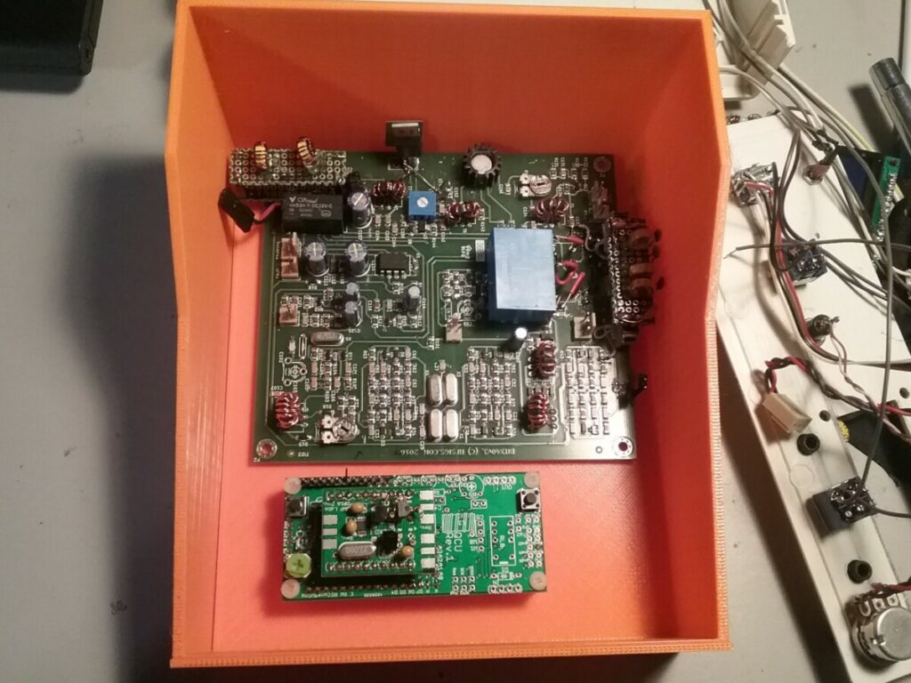
Someday it’ll be a radio! – Feb 2018 Let the hacking begin Don’t mind the BNC, that came off. The QRP Labs Shield and Synth 
Fine for bandpass. 
Not for Low Pass. This is where it all started to fall apart. 
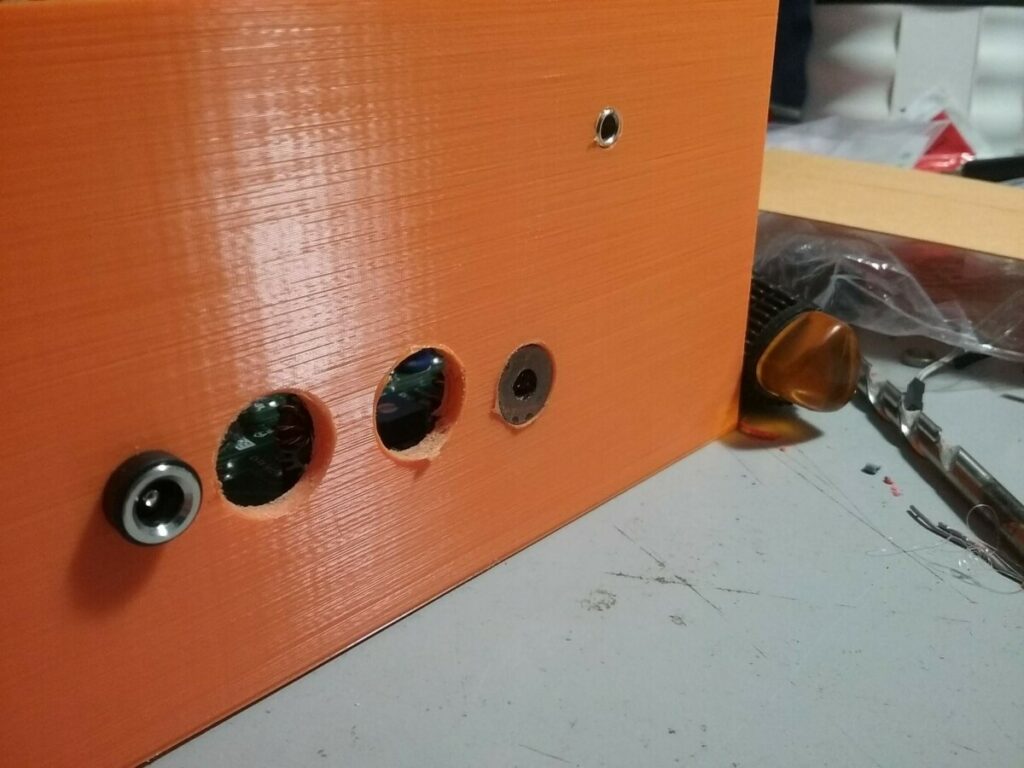
Failed Filter Foibles. An early concept Another early concept shot. This never happened. Clean slate It fits! Barely, thanks to my mods. Drilling the first holes Holes drilled, thingies installed It’s starting to look like a radio! It functions! Kinda The speaker is held in with hot glue and unicorn saliva. In case you’re wondering: Step Drill bit. Hot Glue, oh how I love thee Knobs! And Speaker! The tail end


2 comments
Way to go Ryan, you write a fabulous blog. I got here because of Soldersmoke blog, where your DC RX was shown off. Oh, and the BITX FB site too! So much homebrew that I love it! I am building a W1FB dc rx, been staring at the schematic in a book way too long, and learning Kicad for some PCB etching. Keep your blog going, your a great writer!!
Author
Hey Ed thanks for the comment. I am glad you enjoyed the article! I hope to be doing more soon as I await the release of the QSX. That’ll leave LOTS of room for many articles. Be sure to subscribe to the blog, that way you always get notified of new posts 🙂