
If you’ve been keeping up on the MiscDotGeek YouTube channel or the QRP Labs Groups.io forum, then you’re likely aware that the QCX Mini has had some teething issues. We’ve already covered the C38 problem, and that’s been fully resolved. Instead we’re going to look at the issue that some builders are having: The inability to align the receiver. First we’ll put it in perspective, then we’ll dive into the troubleshooting.
Before you read further
The purpose of this article is to document a troubleshooting procedure. Troubleshooting is an important skill that many lack. Sometimes, the things you think are troubleshooting, well… aren’t. This article serves to highlight a proper troubleshooting procedure for a very specific problem. At some point if there is interest I’ll do a video/article about how to troubleshoot in general. To me, it is a fascinating subject.
If you have an unbuilt QCX Mini, do not be deterred! Build on! And if you DO have a problem, be sure to read all the way to the end.
And One More Thing: This is in no way designed to replace Hans Summer’s official QCX Troubleshooting video, which is the basis for everything I learned about this subject. Furthermore, looking at the DC voltages is often enough to determine which IC is bad. In my case it was not and so it is the subsequent troubleshooting that I am focusing on.
All that being said, there are many QCX Mini’s that never experienced a problem. Let’s put this into…
Perspective
The QCX Mini’s first run has had some trouble. Take into consideration though that some issues are to be expected in the first run of almost any product. Additionally, 997 kits were sold, and a huge amount of people are building right now. It is relatively uncommon for people to say “It worked!” Most will download the directions, build it, and say nothing. This is fine, of course- it’s the expected action. The vast majority of people who post however are going to be those that are having problems. After all, that’s what community driven technical support groups are for.
Furthermore, don’t let this first batch dissuade you from purchasing a QCX Mini from the second batch (which I will definitely be doing). Hans has said that no matter the percentage of people having problems, it’s too many and he’s working to prevent such issues in subsequent batches of QCX Mini’s. He’s taking a two-pronged approach: Beat up his suppliers who have caused so much grief, and stringent QA testing of each and every board that gets shipped in all further batches. In fact, he FIRED the fab house that built the first set of boards!
Troubleshooting QCX Mini Alignment Problems
Now we’ll dive into troubleshooting alignment problems with the QCX mini. To troubleshoot, you first need to understand and be able to reproduce the symptoms. Then you need to understand how the QCX receiver works so that you can take a systematic approach to resolving the problem. The documentation is the best place to go for a description, but I’ll summarize it.
Symptoms
After QCX Mini assembly is completed, the instructions call for going to menu 8.8, 8.9, and 8.10 to minimize the signal strength at each step by turning the trim potentiometers R27, R17, and R24. These work to cancel out the opposite sideband. Or in some cases, they don’t.
The primary symptom is that sideband cancellation is impossible. A secondary symptom is that when nulling out the signals (or trying, anyway) the volume potentiometer goes from about ‘5’ to ’13’ in well under 1/4 of a turn. It’s supposed to take most of the travel to do this.
Other symptoms might be that the audio isn’t getting to the output, so nothing is heard in headphones. That is a different problem that could be related to op-amps, and so the same type of troubleshooting techniques will apply.
Understanding Phasing Cancellation
The symptoms tell us that there is no phase cancellation happening. Essentially, the receiver works in a way that eliminates half of the signal (the sideband we don’t want), and then amplifies what’s left into audio that you hear. For this reason, an untuned receiver overloads all of the audio amplification chain, because there is too much signal (both sidebands) going through the audio chain. So we have to troubleshoot to find out why the phasing sideband cancellation is not working.
Phasing sideband cancellation is something I’ve struggled to understand myself, but tracing the fault in my own QCX has made it far clearer. Let’s take a quick look at it. First, go grab a copy of the schematic and follow along:
http://qrp-labs.com/images/qcx/trouble/circuit.png
Follow the blue line in the schematic. The desired signal comes in from the antenna and is routed through to T1. Imagine that the whole signal is across both windings, and the center tap cuts it in half. Each half is a phase. These two phases are fed to the FST3253 which is what’s being used as the Tayloe Detector. The SI5351 chip also feeds in two phases of the desired frequency. The output of this circuit is the resulting audio, just as you’d have in any Direct Conversion receiver, but four times. Each output is the same audio, 90 degrees out of phase the one before it. 0 and 180 degrees are combined in the I channel for a dual sideband signal. The 90 and 270 degree phases are combined into a dual sideband signal and sent through the Q channel.
The next thing that happens is where the magic is. The two Dual SideBand (DSB) signals are maneuvered around in such a way that the unwanted sideband is cancelled out, thus killing off half the signal.
If none of this is working, then we need to troubleshoot to find out why. First we’re going to take an analytical approach to solving the problem, and then we’ll look at the “shotgun” approach. (Sorry, no firearms are involved!)
Troubleshooting the QCX Mini Op-Amps
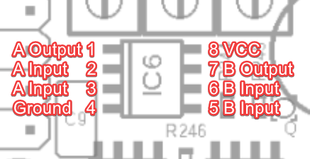
In the QCX circuit, there are two op-amps that take care of the sideband cancellation: IC6 and IC7. In the schematic, they’re shown as IC6A, IC6B, IC7A and IC7B. This is because each IC contains two op-amps. Pin 8 is the power supply, pin 4 is ground. Pins 3 and 2 are the input for the first op-amp, and pin 1 is its output. Pins 5 and 6 are input for the second op amp, pin 7 is its output. IC7 takes care of the I channel, and IC6 the Q channel.
The surface mount devices are what are called SOIC8 packages. You can see them in the picture below. You’ll note that they have 8 pins and that one side of the chip has a bevel that the other side doesn’t have. You can find the chip layout on page 15 of the QCX Mini assembly manual so you can see which is which, but the following may help as well.

If you follow the schematic, you can see how the IC’s are configured:
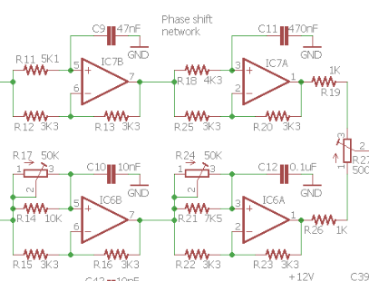
The channels are independent until their signals are combined by R27 at the far right. IC6B feeds IC6A which outputs to R27, and the same for IC7B and IC7A. The difference is that IC6A and B are adjustable which is why in the alignment, you want less signal. That signal you’re nulling is the unwanted sideband. When R17, R24, and R27 are ineffective, that means that sideband cancellation isn’t happening, which means there is a problem somewhere in this circuit.
I showed how I measured the op-amp inputs and outputs in the video below. Essentially, the inputs should have a lower signal voltage than the output. We’re talking about audio signals, not DC voltage. My own op-amps showed fine DC voltage, but one of the inputs on IC7 was abnormally low when measuring the Peak-to-Peak AC voltages.
The best way to check the AC voltages is with an oscilloscope. A simple 200khz scope, linked to the right, is inexpensive and works fine for audio. Check the video for a demonstration:
Replacing the bad IC
Use the same method to find one of the IC’s that not working correctly. You dont’ need to have a fancy oscilloscope to see the phases. It’s enough to see the peak to peak or RMS voltage. If any of the inputs aren’t the same amplitude (voltage) or if the output isn’t higher than the input, then there is likely an issue with that IC.
If you’ve found an IC that seems suspect, then it’s best to simply replace it. Some folks are intimidated because these are surface mount devices, but I’ll be honest: it’s not that bad, even with a plain soldering iron and no extra goodies. The following video shows how I replaced another SMD part that was 16 pin (and was completely unnecessary!). I can tell you, the 8 pins are a lot easier, and that’s saying something!
Finding a suitable replacement for IC6 through IC10
If you replace OPA2277’s with OPA2277’s, you’ll pay a hefty price. They were chosen for the QCX Mini because they have a low current consumption, but they are expensive in the US and many other places. The accepted replacement (and what I used) is the Texas Instruments NE5532D, which is less than a dollar. I got 10 of them shipped from Arrow.com for $13, and half of that was shipping!
It also bears saying one more time: Leave IC5 alone. IC5 is an LM4562 which is not problematic. IC5 is responsible for the high performance of the radio and if it must be replaced for any reason (it won’t) then an exact replacement is necessary.
The Shotgun Approach
In a QRP Labs Groups.io topic about the op amps, Fred Spinner brought up an alternative idea: If you’re having adjustment issues, just replace all of the OPA2277’s. This saves the troubleshooting steps and gets rid of any faulty chips all at once. It’s more work, but if you’re comfortable replacing one, then just replace them all. But here’s the thing:
IF YOU ARE NOT HAVING ISSUES WITH YOUR QCX MINI, DO NOT REPLACE THE OP AMPS
None of this is necessary unless you have issues that are related to the op amps!
If You Need Further Help
If you run into problems and need help troubleshooting, by all means, ask. There is a fantastic support group at https://groups.io/g/QRPLabs/topics where you can get assistance with just about any problem.
I hope you’ve found this article helpful. If you have any of your own tips, please leave them in the comments below. Also, check out the QCX Mini Mini Tip series on YouTube and subscribe if you haven’t already. Thanks for reading, and 73!


4 comments
Skip to comment form
I received my QCXmini recently. 20m band. Works on reception perfectly. Then I noticed that it has less than 1 W of output power. It should have 5 W of output power. The input voltage is 13.8 V. I opened the unit and by tweaking the coils achieved an output of just over 3W on TX. This looks like the maximum.
However, when I put the thing back together, my LCD display is now not working. It is lit but there is nothing on it. The radio seems to be working normally. But I can’t see anything on the display. Everything looks fine with the pins.
Maybe you guys can help me sort this out.
Author
Hey Mathias, thanks for the comment! I’d start by checking all of the solder joints on the control board where the display is. Almost all of my issues have surrounded such things. You also might try removing a turn from the LPF’s toroids, that’s how I got 5w out of mine. For more help, I’d suggest joining the group at https://groups.io/g/QRPLabs/topics. They’re an excellent source of wisdom 🙂
Thank you for the reply!
I somehow managed to increase the output power to 5w. Now the problem is the LCD display. the display turns on but only shows the top line of the boxes themselves. Any suggestion? I would greatly appreciate.
Author
Glad to hear it! That’s probably going to be a cold solder somewhere. Check all connections between the boards 🙂